-
Share:
Contact us
Inquiry
-
E-mail:yuxiatugong@163.comWhatsApp:3236396607
Large-scale, weather-tolerant, protective, long-life reservoir geomembrane liner
Reservoir Geomembrane Liner — Comprehensive Product Introduction
Executive Summary
This document highlights the role of HDPE Reservoir Geomembrane Liner, the reliable performance of Waterproof Reservoir Geomembrane Liner, and the adaptability of Flexible Reservoir Geomembrane Liner as key solutions for modern reservoir applications.
Reservoir geomembrane liners are engineered, impermeable barriers made from polymeric materials that prevent seepage and protect soils and groundwater wherever water is stored above natural ground. For agricultural irrigation reservoirs, municipal potable-water impoundments, aquaculture ponds, flood-control basins, mining process ponds, and industrial equalization tanks, a modern geomembrane provides the highest level of hydraulic integrity with long, predictable service life and excellent resistance to ultraviolet (UV) radiation, weathering, and chemicals commonly present in stored water.
Compared with unlined reservoirs, geomembrane-lined systems typically reduce losses to near zero, translating into measurable increases in usable storage, improved water security through drought cycles, and meaningful reductions in operating costs associated with re‑pumping, make‑up water, and erosion repair. When integrated with proper subgrade preparation, cushioning geotextiles, reliable welding methods, and a structured quality assurance/quality control (QA/QC) program, a reservoir geomembrane liner becomes a durable civil component rather than a consumable. This document provides a comprehensive, practice‑oriented reference that procurement teams, design engineers, contractors, and owners can use to specify, install, operate, and maintain a reservoir geomembrane liner with confidence.
1. What Is a Reservoir Geomembrane Liner?
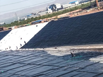
A reservoir geomembrane liner is a continuous sheet of low‑permeability polymer placed over a prepared subgrade to block fluid migration. It is usually supplied in factory‑wound rolls and installed in the field by unrolling, positioning, seaming adjacent panels, and anchoring edges in perimeter trenches or mechanical terminations. While natural clays were historically used to line reservoirs, polymeric geomembranes deliver orders‑of‑magnitude lower hydraulic conductivity, far greater durability against cracking and desiccation, simpler construction logistics, and improved inspectability and repairability over time.
Functional roles of the liner include (a) eliminating seepage losses, (b) separating water from potentially reactive or contaminated soils, (c) protecting embankments from internal erosion and piping, (d) providing a cleanable surface that discourages burrowing animals and root intrusion, and (e) enabling active leak detection and collection if combined with drainage geocomposites. A properly selected liner accommodates the reservoir’s geometry (floor, benches, slopes, and crest), tolerates expected differential settlement, and retains sufficient ductility after many years of exposure.
2. Material Options and Core Properties
Among the available materials, the HDPE Reservoir Geomembrane Liner is the industry’s standard for durability and UV resistance. The Flexible Reservoir Geomembrane Liner offers superior conformability and ease of installation in irregular subgrades, while the Waterproof Reservoir Geomembrane Liner ensures long‑lasting impermeability even under harsh environmental conditions.
Common reservoir liner materials include High‑Density Polyethylene (HDPE), Linear Low‑Density Polyethylene (LLDPE), flexible Polypropylene (fPP), Polyvinyl Chloride (PVC), and EPDM rubber. Each has distinct performance characteristics:
• HDPE — Industry workhorse for large reservoirs. High tensile strength, excellent chemical and UV resistance, and superior long‑term stress‑crack performance. Slightly stiffer, requiring careful layout in tight corners and cold conditions.
• LLDPE — Greater flexibility and conformability, advantageous on complex subgrades or steeper slopes. Broad chemical resistance with very good weldability.
• fPP — Tough and flexible with good thermal range and reduced thermal contraction; often selected where dimensional stability is important.
• PVC — Soft, easy to fabricate, and flexible at low temperatures; however, long‑term UV and some chemical exposures require careful formulation and cover strategies.
• EPDM — Highly elastic, typically used on smaller ponds and aquaculture; usually joined with adhesive splices rather than thermal welding and therefore managed with different QA/QC routines.
Thickness selection depends on reservoir size, service life, and mechanical demands. Typical ranges are 0.75–3.0 mm; for municipal or high‑duty irrigation reservoirs, 1.5 mm and 2.0 mm are common, while 2.5–3.0 mm may be chosen for extremely long lifetimes, high traffic loads during maintenance, or for slopes subject to mechanical equipment. Critical index properties include tensile strength and elongation, puncture and tear resistance, stress‑crack resistance (for HDPE), carbon‑black content and dispersion for UV durability, oxidative induction time (OIT) for thermal/oxidative stability, and hydrostatic resistance (permeation). Laboratory testing is commonly performed to relevant standards such as ASTM and GRI; for example, ASTM D6693 (tensile), ASTM D4833 (index puncture), ASTM D5397 (stress‑crack), ASTM D4218 (carbon black content), ASTM D5596 (carbon black dispersion), ASTM D3895 or D5885 (OIT), and interface friction via ASTM D5321. Specification frameworks such as GRI GM13 (HDPE), GM17 (LLDPE), and GM19 (fPP) are widely referenced in tender documents.
Hydraulic conductivity of intact geomembranes is effectively negligible (often cited in the 10^-14–10^-12 cm/s range). Practical leakage, when it occurs, is dominated by defects (cuts, pinholes, or imperfect seams), which is why design emphasizes robust subgrade preparation, adequate cushioning, conservative welding parameters, and field testing regimens.
3. Design Considerations for Reservoirs
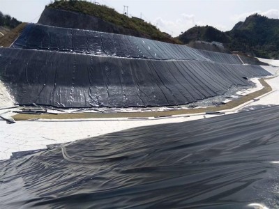
3.1 Geometry and Layout
Reservoirs may be excavated below grade, embanked above grade, or combined (“cut‑and‑fill”). Typical slope gradients range from 3H:1V to 2H:1V for unreinforced soils, with flatter slopes preferred for safe access and to reduce tensile stresses in the liner. The crest or freeboard should account for wind setup, wave run‑up, and operational fluctuations. Panel layout drawings should minimize cross‑slope seams and align long seams parallel to the direction of steepest slope to reduce peel stress.
3.2 Anchor Trench and Terminations
Perimeter trenches provide mechanical restraint against wind uplift and hydrostatic forces, and protect the liner edge from UV and accidental damage. The trench geometry is project‑specific; many designs use a rectangular or trapezoidal cross‑section with sufficient embedment depth and backfill compaction. At concrete structures (intake towers, spillways, or outlet works), mechanical terminations may use stainless steel batten bars with compatible sealants, waterstops, or reglets.
3.3 Wind, Wave, and Thermal Movements
Wind gusts can induce fluttering or uplift on exposed liners. Temporary ballast (sandbags or water‑filled tubes) is used during construction; permanent solutions may include ballast berms, protective cover soils, geocell confinement, or tensioned floating covers in select zones. Wave action concentrates cyclic loads at the still water line; designers may specify thicker liner or protective armoring (e.g., riprap above a cushioning geotextile). Polymeric liners undergo thermal expansion and contraction; designers manage this by installing within an allowable temperature window, providing slack (panel lay‑down “relaxation”), and detailing expansion allowances at penetrations.
3.4 Slope Stability and Interface Friction
Where cover soils, riprap, or concrete slabs overlie the liner, interface friction governs stability. Laboratory direct shear testing (ASTM D5321) on the actual material pairings (e.g., geotextile vs. liner vs. soil) informs factor‑of‑safety calculations. For bare liners, personnel access and equipment traffic on slopes should be restricted or guided by walkways and safety protocols.
3.5 Settlement, Seismic, and Differential Movements
Liners must accommodate subgrade settlement and potential seismic deformations without tearing. Flexible materials (LLDPE, fPP) offer advantages in high‑differential areas, while HDPE’s higher tensile modulus benefits flat, extensive floors. In seismic regions, details should avoid stress concentrations at corners and transitions; fillets and gradual geometry changes reduce strain accumulation.
3.6 Leak Detection and Drainage
For critical reservoirs, a double‑liner with an interstitial drainage/geonet layer allows active leak detection. Electrical leak location (ELL) methods—water puddle, dipole surveys, arc testing—can be integrated by ensuring electrical continuity to subgrade or a conductive layer under the liner. Toe drains and relief features protect embankments by safely routing incidental leakage to monitored sumps.
4. Subgrade Preparation and Cushioning
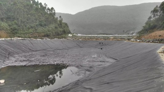
Performance begins with the ground. Subgrade should be graded smooth, compacted to the specified density, and free of protrusions, roots, and sharp stones. Soft zones are proof‑rolled and over‑excavated as needed. Where angular aggregates, desiccation cracking, or root pressure could threaten the liner, a nonwoven geotextile cushion is placed beneath the geomembrane. Geotextile mass per unit area is selected to resist puncture and distribute point loads; values in the 200–600 g/m² range are common for reservoirs, with higher values in rocky subgrades or beneath riprap. In some designs, a geosynthetic clay liner (GCL) may be added under the geomembrane to provide a composite barrier with self‑sealing characteristics against small punctures.
5. Panel Fabrication, Welding, and Field QA/QC
5.1 Panel Delivery and Storage
Store rolls on level ground, off the soil, under protective covers when prolonged sun exposure is expected prior to installation. Handle with spreader bars and core‑friendly slings to avoid telescoping or creasing.
5.2 Seaming Technologies
Two principal thermal welding methods are used for polyolefin geomembranes:
• Hot wedge (dual‑track) fusion: Produces two parallel seams separated by an enclosed air channel. The inter‑seam channel allows rapid non‑destructive air‑channel testing.
• Extrusion fillet welding: Used for T‑junctions, patches, and details around penetrations. Requires surface preparation (grinding/abrading) to expose fresh polymer for bonding.
Welding parameters—temperature, speed, and pressure—are set based on test welds performed at ambient conditions and verified throughout the day. Seaming should avoid ponded water, high winds, or subfreezing temperatures unless procedures and shelters are implemented.
5.3 Non‑Destructive Testing (NDT)
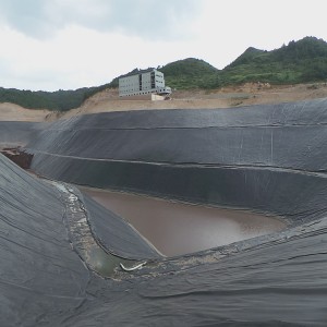
• Air channel testing: Pressurize the dual seam channel and monitor decay over a set period.
• Vacuum box testing: Apply a soapy solution, place a vacuum box with a clear window over the seam, and observe bubble formation indicating leaks.
• Spark testing (holiday testing): For extrusion fillets in certain materials, an appropriate high‑voltage spark tester can reveal pinholes; use only with compatible liners and safety protocols.
5.4 Destructive Testing
Field samples are cut from seams at defined frequencies (e.g., one test per set length of seam). Laboratory or field tensiometer testing evaluates shear and peel strength and failure mode. Acceptance criteria reference the governing specification (e.g., GRI GM13 for HDPE). Repair patches are installed at sample cut locations and any non‑conforming areas.
5.5 Documentation and Traceability
Maintain seam maps, panel layout drawings, welder and machine IDs, calibration records, NDT logs, destructive test results, weather data, and repair logs. This documentation underpins warranty claims and future condition assessments.
6. Ancillary Components and System Integration
• Geotextiles: Cushioning below and protection above; filtration at drains to prevent soil migration.
• Geonets and geocomposites: Provide high‑capacity in‑plane flow for leak detection and drainage behind/under the liner.
• Ballast and protection layers: Sand, gravel, soil cover, or concrete slabs may be used, designed for interface stability and constructability.
• Penetrations and appurtenances: Inlets, outlets, aeration diffusers, and instrumentation penetrations require prefabricated boots, collars, and robust mechanical terminations.
• Floating covers and shade structures: Where evaporation control or water‑quality protection is critical, floating modular covers or tensioned covers can be integrated with the liner perimeter details.
7. Operation, Inspection, and Maintenance (O&M)
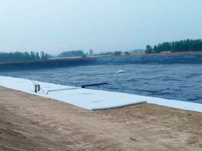
Routine O&M preserves design performance and warranty validity. Establish an inspection schedule after commissioning: monthly visual scans during the first year, then quarterly and after major storms. Key tasks include:
• Check anchor trenches for settlement, erosion, and animal burrows; re‑compact backfill if necessary.
• Inspect seams at high‑stress areas (around penetrations, corners, benches).
• Remove debris, sharp objects, and excessive biofouling; manage algae with approved water treatments compatible with the liner material.
• Monitor slopes for slippage of cover soils or riprap; verify toe‑drain function.
• Record water levels, temperature extremes, and any unusual deformation.
Repairs should use like‑for‑like material, with surfaces cleaned and prepared, patches rounded at corners (no sharp re‑entrant angles), and seams tested. Keep a site‑specific repair kit and trained personnel or a standing contract with a certified installer.
8. Service Life, Reliability, and Risk Management
Service life is governed by a chain of mechanisms: oxidation, UV degradation, thermal aging, stress‑cracking (for HDPE), mechanical damage, and chemical exposure. Modern polyolefin liners formulated with carbon black and antioxidants can deliver service lives of decades when installed and operated within the design envelope. Risk management focuses on preventing point damage (punctures, vandalism), controlling uplift forces (wind), ensuring slope stability (interface shear), and enabling leak detection to avoid small defects growing into significant losses. Many owners adopt a tiered risk framework that defines inspection frequency, leak‑rate action thresholds, and escalation pathways (additional testing, temporary drawdown, or partial relining) to maintain resilience.
9. Environmental and Economic Benefits
Water saved is energy saved. By cutting seepage, the liner reduces the volume that must be pumped from distant sources, thereby lowering greenhouse‑gas emissions associated with energy use. Lined reservoirs stabilize embankments by preventing internal erosion and piping, decrease the footprint required to meet a target storage volume, and reduce the need for chemical make‑up water. From a financial perspective, a life‑cycle cost (LCC) analysis typically shows rapid payback where water is scarce or expensive. Savings accrue from avoided seepage, reduced maintenance of eroded slopes, fewer emergency repairs, and longer intervals between major rehabilitations.
10. Typical Technical Specification (Guide)
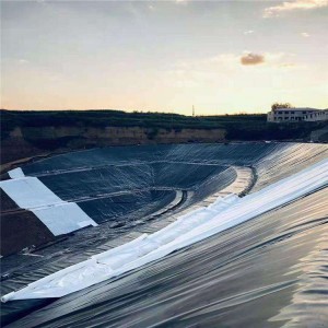
The following guide outline helps buyers and engineers assemble a clear, enforceable specification. Values are indicative and should be tailored by a licensed engineer based on local codes, loads, soils, and water quality.
10.1 Material
• Type: HDPE (conforming to GRI GM13) or LLDPE (GRI GM17), thickness 1.5–2.0 mm for general reservoir duty unless otherwise noted.
• Additives: Carbon black 2–3% by mass; UV stabilizers and antioxidants per manufacturer’s formulation.
• Color: Black preferred for UV durability; surface texture where needed for interface friction.
10.2 Physical Properties (Index Tests)
• Tensile strength and elongation: ASTM D6693, Type IV dumbbells; values per selected specification.
• Stress‑crack resistance (HDPE): ASTM D5397 NCTL meeting or exceeding specification minimums.
• Puncture resistance: ASTM D4833.
• Carbon black content: ASTM D4218; dispersion: ASTM D5596.
• OIT: ASTM D3895 (Standard OIT) and/or ASTM D5885 (High‑Pressure OIT).
• Density, melt index, and dimensional stability: per applicable ASTM.
10.3 Manufacturing and Factory QA
• Manufacturer shall operate an audited quality system with lot traceability. Certificates of Analysis shall accompany each roll.
10.4 Installation
• Subgrade: Smooth, compacted, free of protrusions; engineer approval prior to lining.
• Cushion: Nonwoven geotextile (≥ 200 g/m²) beneath liner where puncture risk exists.
• Seams: Dual‑track hot wedge fusion for production seams; extrusion fillet for details.
• NDT: Air‑channel testing of fusion seams; vacuum box testing of all extrusion seams.
• Destructive testing: Frequency and acceptance criteria per specification; repair and retest all cut‑out locations.
• Terminations: Anchor trench at perimeter; mechanical fastening with compatible sealants at structures.
• As‑built records: Seam maps, test logs, weather, repairs.
10.5 Commissioning
• If specified, perform electrical leak location (ELL) testing under wet conditions with a qualified provider.
• Submit O&M manual and train staff before turnover.
11. Case Studies (Illustrative)
Across agricultural, municipal, and industrial projects, the integration of HDPE Reservoir Geomembrane Liner, Flexible Reservoir Geomembrane Liner, and Waterproof Reservoir Geomembrane Liner has proven essential to achieving water security, minimizing seepage losses, and enhancing sustainability.
Case A — Agricultural Irrigation Reservoir, 38,000 m²
A grower cooperative constructed a 250,000 m³ lined reservoir to feed a pressurized drip‑irrigation network serving 1,600 hectares. The design used a 1.5 mm HDPE geomembrane over a 300 g/m² nonwoven geotextile cushion, with textured liner on slopes to improve interface friction under a 200 mm soil cover. Despite frequent temperature swings (−5 to 42 °C), thermal movement was managed by installing within a 10–20 °C window and detailing expansion allowances at penetrations. Post‑commissioning water‑balance data indicated seepage losses below measurement resolution, and pump runtime dropped 11% compared with the previous unlined earthen reservoir of similar capacity. Payback on lining costs was realized in just under three irrigation seasons.
Case B — Municipal Potable Storage, 12,500 m²
A coastal utility lined a brackish‑to‑potable blending reservoir adjacent to a desalination plant. The project selected 2.0 mm LLDPE to accommodate settlement over soft marine clays. A double‑liner with geonet leak‑collection allowed active leak monitoring, and an ELL dipole survey confirmed leak‑free handover. After three years, periodic inspections reported negligible UV chalking and stable seams; the utility added a floating shade cover to further suppress algal growth and evaporation, demonstrating modular integration potential.
12. Frequently Asked Questions (FAQ)
Q1: How do I choose between HDPE and LLDPE?
A: HDPE offers higher modulus, superb chemical/UV resistance, and excellent long‑term stress‑crack performance—ideal for large, relatively simple geometries and where mechanical robustness under cover is critical. LLDPE is more flexible and better for complex shapes, steep slopes, and areas with differential settlement. Both are widely used; the final choice balances constructability, long‑term movements, and owner preferences.
Q2: What thickness should I specify?
A: For reservoirs, 1.5 mm is a common minimum; 2.0 mm is favored for municipal duty or when higher traffic, cover soils, or long service lives are expected. Very small ponds may use 1.0–1.2 mm; heavy‑duty industrial or long‑life assets may justify 2.5–3.0 mm.
Q3: Can animals or roots damage the liner?
A: A smooth, compacted subgrade and a cushioning geotextile greatly reduce risk. Many owners also control vegetation around the crest and perimeter to limit root intrusion and burrowing.
Q4: How are leaks detected?
A: Non‑destructive tests verify seams during construction. After commissioning, operators can perform periodic ELL surveys (water puddle or dipole methods) and monitor toe drains; in double‑liner systems, interstitial flow meters provide continuous assurance.
Q5: Will sunlight ruin the liner?
A: Quality black polyolefin liners are formulated with carbon black and stabilizers that deliver decades of outdoor durability. Where additional protection is desired, partial soil cover or shade structures may be added.
Q6: Is the liner safe for drinking water?
A: Many products are available with potable‑water approvals/registrations in relevant jurisdictions. Always specify the required certification during procurement and confirm material compatibility with your treatment chemicals.
Q7: How are repairs made?
A: Small defects are cleaned, abraded (if extrusion welding will be used), and patched with rounded‑corner coupons of the same material. Repairs are tested using vacuum box or spark testing (as applicable) before return to service.
Q8: Can we drive equipment on the liner?
A: Direct traffic on exposed liner should be avoided. If equipment access is unavoidable, install temporary protection layers, timber mats, or geotextile plus sand blankets and follow strict traffic corridors under supervision.
Q9: What about freezing conditions?
A: Liners remain functional through freeze‑thaw cycles, but installation windows are narrower. Cold temperatures increase stiffness; welding tents, pre‑heating, and adjusted parameters maintain seam quality.
Q10: How long will the liner last?
A: With correct design and O&M, service lives of 25–30 years or more are common for polyolefin liners. Factors like UV index, temperature profile, chemical exposure, and mechanical loading influence actual longevity.
Q11: Do we need a double‑liner?
A: For potable reservoirs near sensitive receptors or where environmental risk is high, a double‑liner with leak detection offers additional assurance. For agricultural or remote sites with low consequence of leakage, a high‑quality single liner with robust QA/QC may be appropriate.
Q12: What documents should be archived?
A: As‑built panel maps, seam logs, NDT and destructive test reports, material certificates, and repair records. These enable efficient future inspections and warranty claims.
13. Sustainability and End‑of‑Life
Sustainability goals increasingly influence liner selection and project detailing. Some manufacturers offer products with recycled content where performance requirements allow; others publish Environmental Product Declarations (EPDs) quantifying cradle‑to‑gate impacts. During operations, evaporation reduction via covers and leak prevention via composite systems can dwarf the embodied carbon of the liner itself. At end‑of‑life, clean polyolefin liner can often be recycled; where recycling is not available, responsible disposal plans should be documented in the decommissioning strategy. Avoid soil contamination during removal by working within drained, cleaned conditions and bunding work zones.
14. Step‑by‑Step Installation Overview (Field SOP)
1) Pre‑construction submittals: shop drawings, welding procedures, welder qualifications, test plans, and material certificates.
2) Subgrade approval: engineer inspects and signs off; soft spots remediated; geotextile cushion placed where specified.
3) Panel deployment: unroll with wind considered; place temporary ballast; avoid dragging panels over sharp surfaces.
4) Test welds: at start of each shift and after parameter changes; document optimal temperature, speed, and pressure.
5) Production welding: prioritize long, downhill fusion seams; maintain overlap tolerances; protect hot seams from dust and rain.
6) NDT: perform air‑channel tests and vacuum box checks progressively; mark and repair defects immediately.
7) Destructive tests: cut samples at frequencies noted in the spec; test peel/shear; install and test repair patches at cut locations.
8) Details and penetrations: fabricate boots, corners, and transitions; use extrusion fillets with proper surface prep.
9) Terminations: set liner into anchor trenches; backfill and compact; install mechanical terminations at structures.
10) Final inspection and ELL (if specified): conduct wet surveys, verify repairs, submit red‑line as‑builts and O&M package.
15. Example Datasheet (Indicative)
Product: HDPE Geomembrane Reservoir Liner (Indicative Data for 1.5 mm)
• Nominal thickness: 1.5 mm
• Density: ≥ 0.940 g/cm³
• Tensile yield strength / elongation (ASTM D6693): per GM13
• Tensile break strength / elongation (ASTM D6693): per GM13
• Puncture resistance (ASTM D4833): per GM13
• Stress‑crack resistance (ASTM D5397 NCTL): per GM13 minimum
• Carbon black content (ASTM D4218): 2.0–3.0%
• Carbon black dispersion (ASTM D5596): Category 1 or 2
• Standard OIT (ASTM D3895) and/or High‑Pressure OIT (ASTM D5885): per spec
• Surface: smooth or textured (one‑ or two‑sided)
Notes: Values are indicative only—final specification to be project‑specific and code‑compliant.
16. Glossary
• Geomembrane — Synthetic sheet used as a fluid barrier.
• Geotextile — Permeable geosynthetic used for separation, filtration, cushioning, and reinforcement.
• GCL — Geosynthetic clay liner; a thin layer of bentonite encapsulated between geotextiles.
• Fusion seam — Dual‑track thermal weld joining adjacent panels.
• Extrusion fillet — Bead of molten polymer used for detail welding.
• ELL — Electrical leak location testing suite for post‑installation integrity assessment.
• OIT — Oxidative induction time; indicator of resistance to thermal oxidation.
• Interface friction — Shear resistance at the boundary between two materials.
• Freeboard — Vertical distance between water surface and the top of the embankment or crest.
• Anchor trench — Excavated trench designed to secure liner edges.
Conclusion
Reservoir geomembrane liners convert vulnerable earthen basins into engineered storage assets with predictable performance, low losses, and manageable risk. Selecting an appropriate polymer, pairing it with the right subgrade preparation and cushioning, welding with disciplined QA/QC, and operating with a simple but consistent inspection program are the keys to multi‑decade reliability. Whether the goal is boosting farm productivity, safeguarding municipal water quality, or ensuring industrial process stability, a well‑specified and well‑installed geomembrane liner is a proven, cost‑effective solution that pays for itself through conserved water, fewer repairs, and resilient service in the face of climate and demand variability.


 Phone
Phone